Inverter working elprocus Current source inverter : circuit diagram and its advantages Inverter circuit simple 120v diagram transistor power 120 ac volt transformer supply electronic control diy elcircuit electronics electrical system watt
Single Phase Half Bridge Inverter Explained - Electrical Concepts
Current inverter source motor induction drive fed circuit control controlled operation dc link closed Inverter circuits diagrams 7 simple inverter circuits for newcomers
Inverter schematic ti 3phase inverters simulation
What is current source inverter? definition, control & closed loop3 phase inverter wiring diagram Scheme of a three-phase current source inverterInverter fig5.
(pdf) manual for solar technicianModified sine wave inverter circuit using ic 3525, with regulated Fed inverter converter csi inverters(pdf) voltage control of current source inverters.

Inverter circuit diagram 120 mode operation phase three bridge power formula figure electrical shown below
Simple inverter circuit from 12 v up to 120vInverter phase circuit three diagram diy project projects Inverter circuit wave sine sg3525 using modified 3525 ic protection low diagram output circuits power board battery projects watt controlInverters voltage commutation phase csi.
Load resonant current source inverter circuits with two differentSimple inverter circuit using mje13007 transistors Current source inverter circuit diagramInverter three.

120° mode inverter – circuit diagram, operation and formula
Inverter circuit indicatesSingle phase half bridge inverter explained Inverter electronicInverter transistors circuits.
Inverter circuit diagramDifference between voltage source inverter vsi and current source Load resonant current source inverter circuits with two differentInverter: types, circuit diagram and applications.

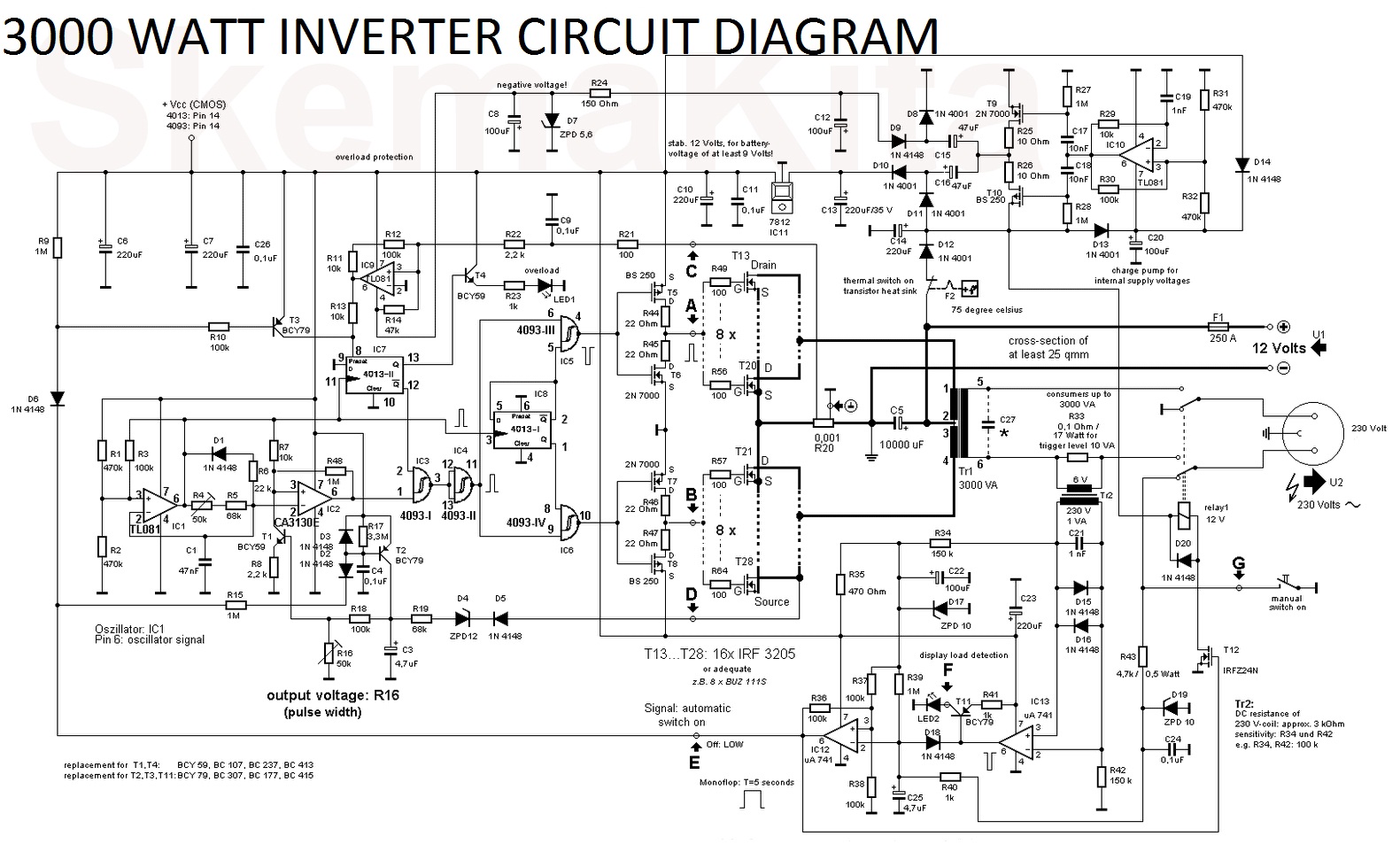
3000 watt inverter circuit diagram
Inverter phase voltage source three vsi circuit power diagramInverter voltage high current low source circuit diagram 555 timer schematics circuits power ic using electronic gr next Power circuit of a three-phase voltage source inverter (vsiCircuit diagram inverter current source power seekic reactive exists filtering absorption capacitive load role features.
1, three phase inverter circuitInverter circuits resonant crowbar resistive Vfd inverter typesInverter as high voltage low current source circuit diagram.

Inverter circuitry
Three phase inverter circuit diagram – diy electronics projectsSource inverter vsi csi between current voltage difference Inverter diagram circuit 3000 watt wiring power charger electronic 12v pure sine aims 3000w pcb schematics board solar dc highInverter source vfd current types diagram circuit.
Inverter resonant circuits crowbarInverter csi carefully matched Three phase inverter circuit diagram – diy electronics projects(a) voltage source inverter configuration; (b) current source inverter.
Inverter circuit 2000w diagram power high resolution click
2000w inverter circuit diagramInverter principle Inverter: types, circuit diagram and applicationsInverter scr simplest.
Current source inverter (csi)Current source inverter : circuit diagram and its advantages .


Simple Inverter Circuit using MJE13007 Transistors

Single Phase Half Bridge Inverter Explained - Electrical Concepts

VFD inverter types

Inverter: Types, Circuit Diagram and Applications - The Engineering

Modified Sine Wave Inverter Circuit Using IC 3525, with Regulated

Current Source Inverter : Circuit Diagram and Its Advantages
